

Jul. 21, 2021
Mechanical Parts & Fabrication Services
The symbol for a control valve is a combination of the appropriate valve symbol and actuator symbol. Control valves can be configured in many different ways. Now, when you look at the symbols on the drawing, it just indicates that a certain type of valve is used, but it does not give you information about the type of valve. Whether it is a gate valve, globe valve, plug valve, or ball valve there are special symbols that I will always explain to you below in conjunction with the pictures.
This is about the P&ID and isometric symbols for several common valves.

Before analyzing the ball valve symbol, I need to briefly introduce the ball valve. A ball valve uses a hollow, perforated, rotatable ball to control the flow through it. The ball valve is rotated by an actuator that drives the valve handle, which in turn rotates the ball about an axis perpendicular to the flow of water. When the ball's hole is parallel to the fluid, it is open and there is no obstruction in the pipe to achieve maximum flow, and when it is rotated 90 degrees in the opposite direction by the valve handle, it is closed. This quick control switch function is also called "shut on-off valve".
You can see by the picture above that there are two P&ID symbols for one ball valve. The reason for this is that the P&ID and contour plot symbols change from company to company. Therefore, if you change companies, you should be aware of this. Similarly, you can see the ISO symbols for butt, flange and socket end ball valves.

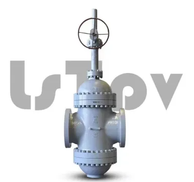
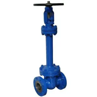
In the picture above, you can see the gate valve. Now look at the P&ID symbol for the gate valve. It is a modification of the generic valve symbol by inserting a vertical line between two triangles. The three symbols shown below are the gate valve symbols used in the contour diagram. The first is the butt weld end, the second is the flange end valve, and the third is the socket end connection.
Suggested reading:

In the picture above, the symbol is an angle valve. In most cases, the shut-off valve is used as an angle valve. The next symbol is a relief valve, which is used to protect the piping system or equipment from overpressure.
Nowadays, breather valves are used for cone-top tanks. This valve has the function of a relief valve and a vacuum valve. In the event of overpressure, the valve relieves pressure, while in the event of a vacuum being created in the tank, the valve allows air to enter the tank. It goes in and out just like breathing air.
The vacuum valve prevents damage to the equipment from negative pressure. Pilot-operated relief valves work only as relief valves, but are used in large size pipelines. In this type, a small relief valve is used to operate the main relief valve. This arrangement is cost effective in large size relief operations.
Realated reading:
How do I know if my Hydraulic Solenoid Valves is bad?
Previous: Some knowledge about compressors
Related Articles
If you are interested in sending in a Guest Blogger Submission,welcome to write for us!

All Comments ( 0 )